2D Pong
A little while ago, I made a PCB business card for a colleague, with a few blinking lights. It came out great, but I wanted to try and do something more interactive. The core idea is that the purpose of business cards is quite unclear these days -- originally, they were meant to communicate contact information, but smartphones handle that better now. Perhaps I can repurpose them to communicate something else about me!
Anyway, I thought that I would make a business card that plays something like Pong. I had always wanted to make a small game with the attiny10!
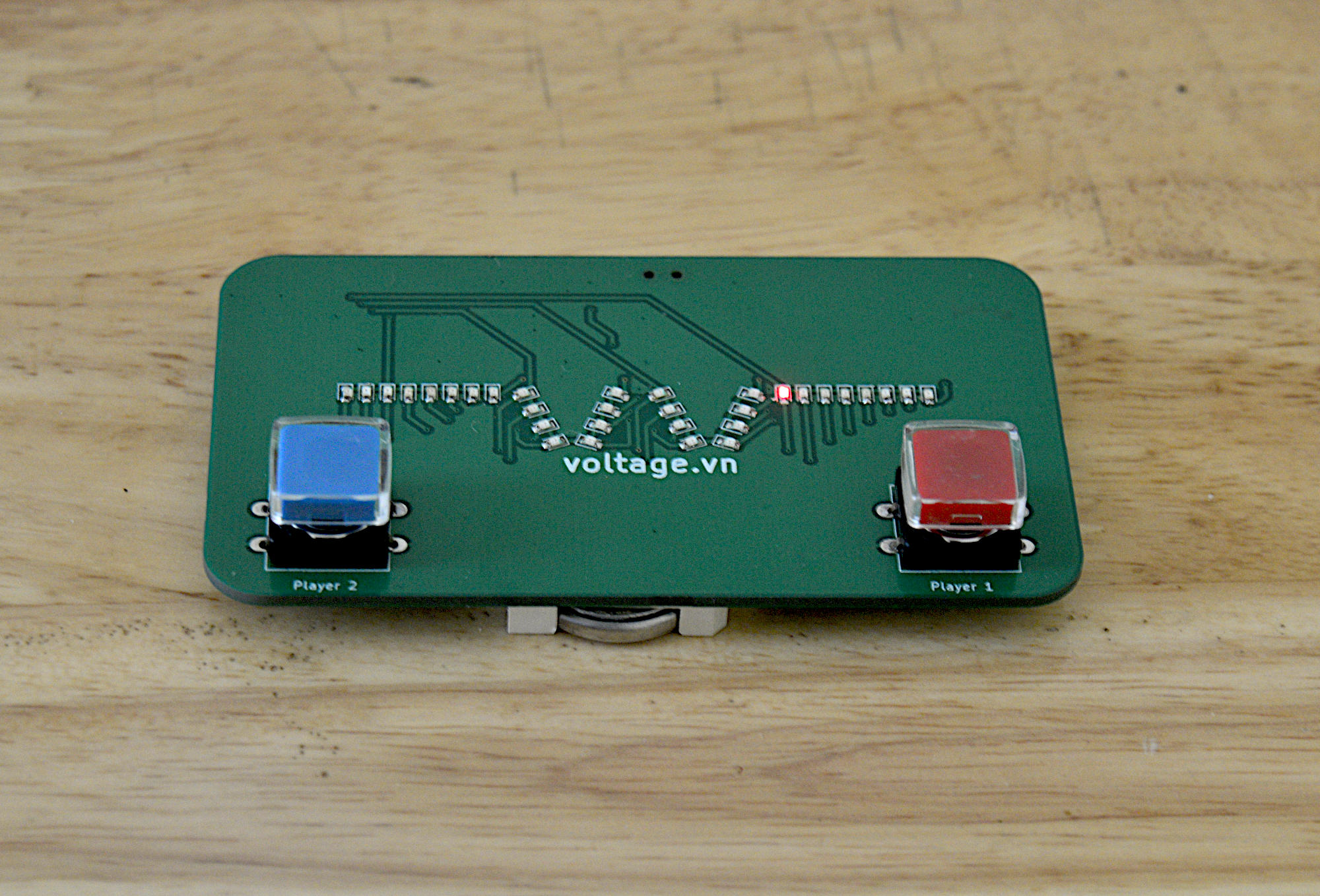
While it would have been possible to build a classic Pong engine with an LED matrix, I decided to go for 2D Pong -- the ball travels down a line of 32 LEDs, and you have to time a button press to hit it back. On every hit, the game would run faster and faster. I thought this would be much more practical on a business card form factor: controls to move a paddle left/right would have been very cramped, but there's enough room for two pushbuttons!
2D Pong has been done by several other people, but I wanted to do in in a particularly low-cost way. I started by thinking about what corners I could cut...
- Attiny10 for the MCU (of course)
- The attiny10 only has 4 gpio, so a TM1640 to control more LEDs
- Power via 2x CR2032
- Control by 2x pushbuttons
- A little SMT power toggle switch
Design Goals
Even though I'm not going to be handing out these business cards, I want them to say something about the way I work. So using a hobby MCU board by copying someone else's code (or using an LLM) would be rather pointless. In any case, while that type of design looks clever at the surface, it is usually quite impractical in terms of power consumption, complexity, and parts cost.
I want to show that I care deeply about what I do. So, I chose parts that get the job done cheaply and effectively.
LED Control: TM1640
The TM1640 is a fun chip, you can control up to 16x8 LEDs with it, and it costs around 25 cents. I used it extensively in my earlier electronic Catan board game build. Like many Chinese ICs, you really must read the datasheet carefully though, and pay careful attention to the timing diagrams.
In my first pass of writing a driver for it in assembly, I made a silly mistake -- the data line was expected to rise, pause, and fall while the clock line was logic HIGH to indicate the termination of a command. The first time around, I did not realize it was latching in on rising edge, I had thought that it only had to be logic HIGH. This meant that any command ending in a 0 would work, and any command ending in 1 would fail! I also got the bit order wrong the first time around, but that was quick to recognize and fix. Anyway, after looking carefully at the timing diagram in the datasheet, I spotted my error.
Power: 2x CR2032
The two CR2032 cells in series are a compromise. They can output between, say, 5.8 and 6.4 volts between them. An ordinary diode with a voltage drop of 0.7V will get that very nicely within the voltage tolerances of those two chips. It may be possible to run everything off a 3V supply, but I did not try yet (the TM1640 is not rated for that).
GPIO: None to spare!
The first really gnarly problem though, was that by default, the attiny10 had only 3 GPIO : the fourth one is the RESET line. The TM1640 requires two of them (DATA,CLK) and the two user buttons should have another two. This presents us with two options:
1. Use the ADC and some resistors to connect two buttons to a single GPIO. Four voltage levels will correspond to the four possible states of the system.
2. Disable the RESET pin to claim the fourth GPIO
Option 1 meant that I would have to either poll the ADC or (more likely) trigger an ADC read on analog comparator interrupt. However, the ADC costs power and time to run, and there will be a lot of weird state management around how often different players can press buttons. So it's not a great choice in terms of power consumption, elegance, or complexity. It would work though.
Option 2 lets me use pin change interrupts, which mean better sleep modes, and I can use the pin change interrupt masks to manage the state of both players -- just re-enable them when they're allowed to press the button again. If we let players trigger button presses whenever, you could just press your button very quickly and never miss the ball! So this is elegant, simple, and has no power wasted -- but there's a catch. Setting the fuse that disables the RESET line means you lose the ability to reprogram the attiny10.
At $0.36 each, I could just use up a chip every code revision. In fact, many low-cost microcontrollers are one-time writable, and this is a normal development flow. However, I'm a cheapskate, so instead I built a high-voltage programmer.
The high voltage programmer applies a 12V pulse to the attiny10's reset line, forcing it into a mode that can be reprogrammed. The high voltage programmer then clears the fuse that disables the RESET line, and I can then flash my next code revision to the chip normally. These are two separate steps, in order to avoid any possibility of a mistake that costs me an expensive AVR programmer.
With that particular issue circumvented, I could use the better GPIO technique, without burning through 50 chips!
A Bit of Difficulty
With the main architectural issues figured out, I thought the rest would be easy. Just set an interrupt on timer compare match, wake the MCU from sleep, process one game tick, and go back to sleep. If a player hits the ball, decrease the timer match value so the game speeds up with each hit. Finally, disable the pin change interrupts for each player when they press their button, only re-enabling them after N game ticks (so you can't just mash the button).
The method is simple enough, I wouldn't even need to use RAM and could just hold the whole game in the CPU registers! Of course, there were some more problems I hadn't thought of yet.
The next issue was a actually bit harder. I had connected PINB2 and PINB3 to the user buttons. These were externally pulled-up and in theory, would generate an interrupt on any change. However, only one button worked in some contexts! I checked my pin change interrupt mask, and indeed I was sometimes clearing bits incorrectly in the PCMSK register. Not a big deal, just set or clear the bits explicitly.
...but setting bit 3 in PCMSK got me an "operand out of range" error in the assembler. Checking the datasheet though, it was not out of range at all, this bit definitely exists and is valid to set!
So this looked like a bug in the assembler! I had not found one of these in nearly 20 years, but I set about confirming it:
LDI R16,(1<<PCINT2) | (1<<PCINT3)
OUT PCMSK, R16 ; enable pin change interrupts on both pins PB2 and PB3. This works fine!
-----
SBI PCMSK, 0b00000100 ; works and enables PCINT on PB2
SBI PCMSK, 0b00001000 ; returns operand out of range and fails to assemble!
-----
IN R16, PCMSK ; Load in the value of PCMSK into a temp register
SBR R16, 0b00001000 ; set bit 3 in it
OUT PCMSK, R16 ; This correctly enables the pin change interrupt on PB3!
So yeah, looks like a minor bug in the assembler, but loading PCMSK into a temp register, setting the bit explicitly, and then moving it back out is a reasonable workaround and only costs an extra 2 CPU cycles. This might have been fixed in a later version of Microchip Studio, I'm using a pretty out-of-date version. Sending a support request requires an account, which requires quite a lot of personal information to create, I gave up on reporting it.
Well, at least now it worked:
In the end, these did turn out cheap enough that I can give some away to family and friends. The 32 LEDs take a little while to solder, but not too bad!